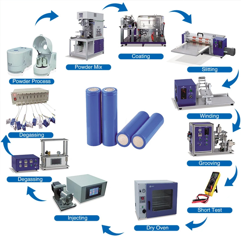
Battery Cell Manufacturing Process
In order to engineer a battery pack it is important to understand the fundamental building blocks, including the battery cell manufacturing process. This will allow you to understand some of the limitations of the cells and differences between batches of cells. Or at least understand where these may arise.
Lets Start with the First Three Parts: Electrode Manufacturing, Cell Assembly and Cell Finishing
1. Electrode Manufacturing
Lets Take a look at steps in Electrode Manufacturing
Step 1 – Mixing
The anode and cathode materials are mixed just prior to being delivered to the coating machine. This mixing process takes time to ensure the homogeneity of the slurry.
Cathode: active material (eg NMC622), polymer binder (e.g. PVdF), solvent (e.g. NMP) and conductive additives (e.g. carbon) are batch mixed.
Anode: active material (eg graphite or graphite + silicon), conductive material (eg carbon black), and polymer binder (eg carboxymethyl cellulose, CMC)
N-Methyl-2-pyrrolidone (NMP): this is a toxic substance, widely used in the plastics industry as it is nonvolatile and able to dissolve a wide range of materials. NMP residual will be a Quality Control test downstream (Gas Chromatography-Mass Spectrometry can be used to test sample) as that will affect cell performance reactively.
18650 21700 26650 32650 Cylindrica Cell productio recta
Challenges
- Homogeneity of the mix
- Ensuring low ppm H2O – suppliers will be asked to guarantee a low ppm
- No breakup of the particles
- Particle and pore size distribution will be targeted with suppliers or via in process Milling
- Some developments concentrate on how to produce dual layers (to form a quasi-heterogeneous bi-layer) to aid electrolyte soaking. The calendaring process can achieve this to a degree.
- Moving from a batch mixing process to continuous mixing
- Ensuring no alien particulates are in the mix
- Magnetic filters often used to remove metal particles, this will only work down to a certain size
Step 2 – Coating
The anode and cathodes are coated separately in a continuous coating process. The cathode (metal oxide for a lithium ion cell) is coated onto an aluminium electrode. The polymer binder adheres anode and cathode coatings to the copper and aluminium electrodes respectively.
Challenges
- Controlling thickness and thickness over time
- control across the width of the web can be more challenging than control along the length
- One of the biggest challenges is getting the edges right:
- Getting the width exactly right down to 0.1 mm –> Shim adjustments can solve this
- Avoiding/Controlling any “Fat Edges” i.e. thickness build ups at the edges –> Also shim adjustments
- Making sure the edges are always straight, and do not show waviness –> Slot die distance to the substrate, and slot die angle need to be controlled and adjusted correctly.
- Foil surface oxidation homogeneity can add variance to the challenge
- Controlling foil moisture levels
- Besides thickness, tensiometer peel tests and even indentation resistance (hardness test) might be used to further qualify the coating integrity
Step 3 – Drying
Immediately after coating the electrodes are dried. This is done with convective air dryers on a continuous process. The solvents are recovered from this process.
Infrared technology is used as a booster on Anode lines.
Challenges
- Centre to edge homogeneity of drying process
- Recovering solvent
- Avoiding cracking
Step 4 – Calendering
This is a rolling of the electrodes to a controlled thickness and porosity.
Challenges
- Controlling uniform thickness
- Avoiding cracking
2. Cell Assembly
Lets Take a look at steps in Cell Assembly below
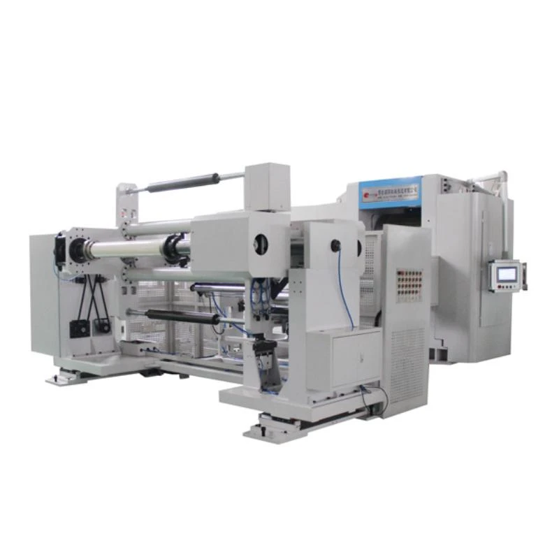
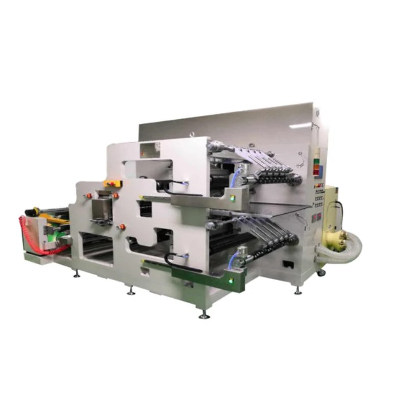
Step 5 – Slitting
The electrodes up to this point will be in standard widths up to 1.5m. This stage runs along the length of the electrodes and cuts them down in width to match one of the final dimensions required for the cell.
It is really important that no burrs are created on the edges of the electrodes during this process as they can cause damage to the separator and a possible short-circuit at a later date.
Challenges
- Avoiding burrs on edges
- Insulation tape may be applied here to mitigate foil to foil shorts from burrs
- Ensuring no loose metallic particles contaminate coatings
Step 6 – Final Drying
The electrodes are dried again to remove all solvent content and to reduce free water ppm prior to the final processes before assembling the cell.
Step 7 – Cutting
The final shape of the electrode including tabs for the electrodes are cut. At this point you will have electrodes that are exactly the correct shape for the final cell assembly.
Challenges
- Avoiding burrs on edges
- Ensuring no loose metallic particles contaminate coatings
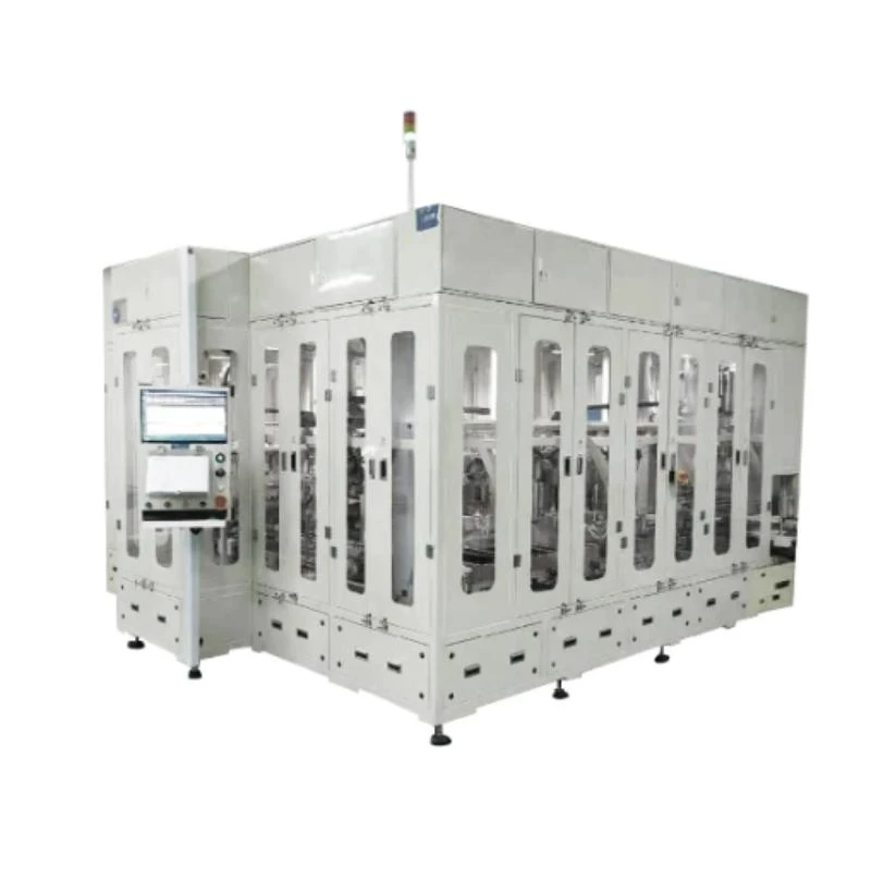
Step 8 – Winding or Stacking
In a cylindrical cell the anode, cathode and separator are wound into a spiral. For pouch cells the electrodes stacked: anode, separator, cathode, separator, anode, separator etc.
Some prismatic cells have stacked electrodes and some have a flat wound jelly roll.
Challenges
- Alignment of layers
- Avoid punctures of separator
- Separator folding
- lots of countermeasures applied over time like separator envelope welding not all manufacturers countermeasure in this way
- Check humidity
- an important test that should be done before assembly and before the filling stage, is checking the humidity of the separator
Step 9 – Terminal Welding
The anodes are connected to the negative terminal and the cathodes to the positive terminal. The process and robustness of this joint are important to understand as welding the cell to busbars can damage the internal welds.
Challenges
- Trimming of tabs and avoiding any burrs or particles being left behind
- Gathering all of the foils and presenting them to the welder
- Aligning gathered electrode foils with tab
- Weld position alignment, whether that is Laser Alignment, spot weld or ultrasonic horn and anvil alignment
- Wear of electrodes / horn / anvil
- Consistent energy burst, energy oscillation, changes in materials or even surfaces
- Ensuring no sputter contaminates cell
- Ensuring good consistent electrical connections
Step 10 – Canning or Enclosing
The electrodes either as a roll or pack of stacked layers are loaded into the can or pouch. Depending on the cell format will change how this canning or enclosing process is completed.
Share
-
Lithium Battery Welding Machine | High-Precision, Fast, SafeNewsNov.17,2025
-
Aluminium Guide Roller | Anodized, Lightweight, Low-NoiseNewsNov.17,2025
-
Tofu Cat Litter Bulk – Eco, Low-Dust, Fast Clumping SupplyNewsNov.17,2025
-
Equipment for Lithium Cell Assembly | Automated & PreciseNewsNov.10,2025
-
Square File Tool – Precision Cut, Hardened Steel, VersatileNewsNov.10,2025
-
Lithium Ion Battery Assembly Machine | Automated, High-SpeedNewsNov.10,2025
